MR Hardware: Difference between revisions
imported>Bobd |
imported>Bobd |
||
| Line 192: | Line 192: | ||
To reiterate-- the physio that are recorded in the physio files starts 30 seconds '''before''' you press the 'start scan' button (yes, it's psychic ;), which always more than 30 seconds before scanning actually starts. It could be substantially longer if you do external triggering. In that case, you'll get some extra physio data recorded during the time between you press start scan and you send your trigger. But the recording does '''stop''' when the scan is prescribed to stop (even if you abort the scan prematurely). So, to synchronize physio and scan data, chop off the extra physio data at the beginning of the file. And if the scan was prematurely aborted, you'll need to take that into account too. | To reiterate-- the physio that are recorded in the physio files starts 30 seconds '''before''' you press the 'start scan' button (yes, it's psychic ;), which always more than 30 seconds before scanning actually starts. It could be substantially longer if you do external triggering. In that case, you'll get some extra physio data recorded during the time between you press start scan and you send your trigger. But the recording does '''stop''' when the scan is prescribed to stop (even if you abort the scan prematurely). So, to synchronize physio and scan data, chop off the extra physio data at the beginning of the file. And if the scan was prematurely aborted, you'll need to take that into account too. | ||
At the CNI, we attempt to do the basic processing on the physio files generated by your scans. The files are read and regressors are computed. These regressors can be used to regress out the physio noise, or they can be used to de-noise the raw data. For details, see [https://github.com/cni/nims/blob/master/nimsutil/physio.py physio.py] in the NIMS repository. | |||
= Scan Triggers = | = Scan Triggers = | ||
Revision as of 15:50, 12 April 2013
MR Scanner
The MR Scanner is in room 065 of the CNI suite in Jordan Hall. It has its own wiki page.
Stimulus Presentation
Flat Panel (30")

The 30 inch diagonal (76 cm, 16:10 aspect ratio) flat panel display was built by Resonance Technology. This particular system is not described on their web-site, but was made upon request. We contacted the vendor, and they built a display for our needs. The display system is based on the Samsung SyncMaster 305T (here's the manual for that display, and a review with some additional information). The LCD panel is similar to that used in the Dell Untrasharp U3011 and the HP ZR30w, but the Samsung has an LED backlight. At the moment, the display is positioned at the back of the bore (70cm from the top shroud around the bore), with a total viewing distance of 190cm. The display width is 25.5 inch (64 cm). The total field of view at this distance is about 20 deg wide.
The display has a native resolution of 2560x1600, 7ms temporal response, and 10-bit color rendering. With a field of view of 30 deg (22) this produces about 80 (110) samples per deg of visual angle. The maximum luminance of the display is 329 cd/m^2 (red is 88, green is 117, and blue is 124 cd/m^2). You can get the calibration data that Franco Pestilli collected on July 18, 2011 in a mat-file: LCD_gamma_20110718.mat.
The display is driven by a dual-link DVI-to-fiber converter to pass clean digital signals into the scan room. If you do not drive the system with a dual-link capable computer, you can not achieve the native resolution. In that case, we suggest that you use 1280x800 (half-native). Note that you must drive this system with a digital signal (DVI-D, dual-link DVI-D, or HDMI via a HDMI-to-DVI-D adapter such as the one found in the CNI control room). A simple VGA-to-DVI adapter will not work, as it outputs analog DVI-A signals. Unfortunately, we have not found a VGA-to-DVI-D converter that works reliably with this system. If your laptop does not have a digital output (DVI, HDMI, or display port), then it might be time to get a new laptop!

The display is mounted on a custom-built 80/20 stand that allows it to straddle the back of the patient table (Steven Engineering supplied the 80/20 pieces and helped identify the MR-compatible connectors). It's inverted and viewed through a double-mirror, so the image orientation as seen by the subject is properly oriented. That is, you do not need to invert or mirror-reverse your stimulus for it to be seen correctly by the subject. This stand has recently been modified to allow it to be easily moved aside so the new 47 inch 3D display can be used.
In order to mirror your laptop display with the flat panel they need to be set to the same resolution, otherwise the flat panel display in the control will appear black and give an out of range error (the LCD screen inside the magnet rooms seems to continue to work properly).
Here are some additional measurements of the visual distance (distance from eye to approximate center of screen) courtesy of Matthew Sacchet. These numbers likely have a bit of measurement error (perhaps unavoidable?), but maybe they might be helpful anyway. The standard 2-mirror viewing apparatus was used. The eye to first mirror measurement was taken from the eye to the midpoint of the short side of the first mirror, roughly aligned to the line of sight.
30” Screen
-64.2cm width, 40.2cm height,
-visual distance: 184.4cm from mirror2, 6cm mirror2 to mirror1, 15cm from eye to mirror1 = 205cm (205.4cm)
47” Screen
-103.8cm width, 58.6cm height
-visual distance: 256.1cm from mirror2, 6cm mirror2 to mirror1, 15cm from eye to mirror1 = 277cm (277.1cm)
3D LCD display (47")
We now also have a 47" 3D LCD display from Resonance Technology. The older 30 inch LCD display has been remounted on a sliding mechanism so that it can be slid in and out of the way of the new display, allowing researchers to choose which display to use. We encourage all new studies to use the new display, as the old one will eventually be retired.
* 1920x1080p
* high frame rate (claimed to be 240Hz)
* LED backlight
* 8-bit color resolution
* field of view comparable to the current LCD (maybe slightly bigger)
The 3D technology employed is Film-type Patterned Retarder (FPR). To see 3D effects, subjects will need to wear passive polarized lenses. The screen can, of course, present non-3D stimuli too.
MRI Compatible Glasses

For participants who wear glasses, CNI has a set of interchangeable lenses that are used with an MRI compatible plastic frame. The frame and lenses are located in the open shelving above and to the left of where the screening forms are located. We have lenses for both near-sighted (-0.5 to -8.0 in .5 step increments) and far-sighted (+.5 to +8.0 in .5 step increments) vision corrections. The lenses are made of hard polycarbonate plastic and are not breakable. The easiest way to install the lenses into the frame is insert the lens from the back first into the edge by the ear piece and then snap in the lens by the nose. If the participant does not know his/her glasses prescription we have a lensometer that can determine that. Basic instructions for use of the lensometer are in the next section. There is also an eye chart posted on the door to the equipment room where participants can test their vision with the MRI glasses. Have the participant stand right in front of the lensometer (about 10 feet from the chart) to use the chart.

Lensometer
To determine glass prescription strengths for MRI participants CNI has the AL200 Auto Lensometer. Is is located in the CNI control room area. There is both a User's guide and a quick reference sheet next to the lensometer. The lensometer is currently set up to read a single vision lens. There are settings available to read either bifocal or progressive lenses, but they are not typically used as only the distance portion of the lens needs to be measured.
Here is a basic how-to from the Reichert user's guide.
-
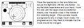
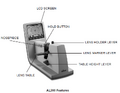 The key parts of the lensometer.
 -
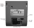 Turn on the lensometer using the switch on the back panel. The AL200 will do a calibration check; do not place any lenses or obstructions in front of the aperture during calibration.
 -
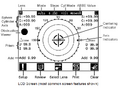
 The AL200’s default measurement mode is Single Vision, Automatic. This mode is used for fast, easy measurement of a pair of single vision spectacle lenses. You're now ready to measure the right lens, indicated by the 'R' on the upper left side of the screen.
 -
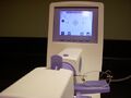
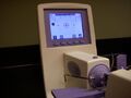 Place the spectacles on the lens table and secure the right lens with the lens holder. Using the table base levers and your hand, move the lens until the large cross is positioned directly over the small cross in the middle of the centering target.
 -
 If you insert a progressive lens in single vision mode, the progressive icon may flash to indicate that the mode should be changed. NOTE: Place the glasses so that lenses are toward the front and the ear pieces toward the back.
 -
 When optical center has been located, the AL200 tone will sound and the measurements will be locked on the screen. Upon removal of the lens the AL200 will automatically switch to the left lens, indicated by the highlighted L on the upper right side of the screen.
 -
 Repeat the measurement process for the left lens. All measurements will remain on the screen until the operator chooses to print or clear the data.
 -
 The number that appears in the Sphere location is the correction number that you will use in choosing the lenses for the MRI glasses.


Auditory System


The auditory system at the CNI uses the Newmatic audio amplifier to drive piezo transducers. Normal sound-attenuating headphones (even those marketed as 'slim'), do not fit in our Nova 32-channel head coil. So, we installed two different sets of ultra-slim transducers. Our primary system uses bone conduction to deliver sound to the subject. For this system, we place piezoelectric transducers directly on the scan subject's cheeks, just in front of the ear. The subject wears sound-attenuating earplugs as usual, and hears the audio stimuli via bone conduction. This system is the only one that reliably fits in the 32-channel head coil. We have found it to be ideal in terms of subject comfort as well, since they can wear ear plugs to block the scanner noise. We recommend that you use the light-weight memory foam pads (the red or white ones) for padding around the ears/head (if padding is needed – the participant may already be snug enough in the head coil). Using the thicker/heavier-weight memory foam pads can push the headphones against the participant’s head in a painful way. Also, please be sure to use sanitary covers. They can be found in the shelves in the scanner room. Use some medical tape to secure them.
The second system uses air tubes that penetrate earplugs and operate much like earbud headphones, except that the sound is delivered through the tubes. Most groups prefer the bone conduction system, but some have found that it is difficult to properly place the transducers for a few subjects, and thus revert to the air-tube system for these subjects.
We have not calibrated the frequency response of either system, but from our own qualitative experience, both have significant attenuation of the higher frequencies (as expected for these kinds of transducers). However, speech stimuli come through fine and both male and female voices sound clear and are fully intelligible.
Both systems are driven by the black Newmatic amplifier box. To set up the audio, plug in the audio cable into your computer’s headphone jack. Make sure that your computer’s sound is turned on. We recommend that you turn your computer’s sound to a high volume, and then use the volume control on the Newmatic amp to adjust the subject's volume. For speech stimuli, we recommend setting the volume to about 6 or 7 to start with, and then adjust as needed. You can use the volume on the black speaker to adjust the volume in the control room (i.e., what you hear). This won’t impact the volume settings for the participant.
We recommend that you test the sound before your participant comes in and also with your participant before you start your experiment (ask them to position the headphones such that they can hear optimally). The Carstensen lab has had good experience using an online violin tuner as the sample sound, for example, this one: [1].
If you need to talk to your participant during the experiment WHILE the sound is also playing, you will want to use the “Talk” button on the black microphone to the left of the GE console, rather than the regular “Talk” button for the intercom. If you are using audio for your experiment, but you want to talk to the participant while the sound is not playing, you can use the regular intercom “Talk” button.
Troubleshooting the audio: If you/your participant cannot hear a sound through the headphones, and you have made sure that the audio cable is plugged in, that both your computer's volume is set to high, and that the Newmatic sound system is turned on and set to a reasonable volume level.
Contact the CNI staff if you need help setting up the auditory system.
Olfactometer

The CNI has a 32-channel olfactometer that can deliver oderants to scan subjects with high temporal precision. The device is controlled via USB using custom software. Before using it, you must run the oderant capillaries and airflow tubing through the waveguide tubes in the equipment room and connect them to the glass mixing chamber. The mixing chamber should be placed on the subject's chest so that the airflow is directed toward their nose. This system is currently maintained by the McClure lab. Please contact them, or the CNI TA for details on using this device and purchasing oderants.
Subject measurement
fORP Response Box
We have a modular response box system (fORP 932) from Current Designs. With ths system, you can swap out various response devices. The output from any of these devices is available from the fORP box via USB. The device emulates a USB keyboard. (Note that we have found more reliable operation with PsychToolbox by using the "USB HID NAR" mode rather than the "USB HID KEY" mode. With KEY mode, some keypresses are missed.) We have confirmed that the fORP 932 USB interface is polled at 1kHz. The device itself has sub-millisecond time resolution (see the fORP FAQ). We estimate that this system provides response time measurements with a precision and reliability of about one millisecond.

The response devices that we currently have are:
- scroll-wheel device
- bimanual button boxes
- 4-button stick-style response device
- 5-button diamond button box
- 5-button curved button box
- trackball device
If you have a need for a different response device, just let us know.
To use a response device at the CNI:
- Plug the desired device into the black fiber-optic connector on the right side of the front of the magnet bore
- Locate the silver box (labeled fORP) in the control room to the right of the GE console.
- Push in the knob on the right front side of the fORP box to enter menu mode. For the following instructions, you will turn the knob to scroll through the menu choices, and then push in on the knob to select your choice. (See this guide for more details on using the fORP 932.)
- Turn the knob until the word "yes" is underlined then push the knob to select "yes"
- In the "mode select" menu that appears next, select "manual config"
- In the response device menu, turn the knob to scroll through the choices until you find the device that you connected in step 1:
- 4-button cylinder: select HHSC-cyl-5
- 5-button diamond: select HHSC-1x5-D
- 5-button curved: select HHSC-1x5-C
- bi-manual 4-button keypads: select HHSC-2x4c
- scrollwheel: select HHSC-SCRL1
- trackball: select HHSC-TRK-2 (for mouse emulation)
- Select USB in the next display by pushing in the knob.
- Select the desired output mode. For the cylinder or keypads, this determines the mapping between the buttons and the keypress that is generated. E.g., HID-NAR-12345 will map the 4 cylinder buttons to the four number keys, 1-4. NAR means "no auto release". In NAR mode, the keypress is maintained as long as the button is pressed. In the non-NAR mode, a brief keypress is generated, even if the button is held down. We find that NAR mode works better with PsychToolbox. In non-NAR mode, it can miss the very brief keypresses produced by auto release. For a description of other modes, see the Current Designs support site.
- Setup is now complete.
PST Response Device

We also have a bi-manual response device from PST. Like the fORP, this device connects to the stimulus computer via USB and shows up as a keyboard.
CNI Touch-pad

We designed and built this MR-compatible touch pad. It uses a KEYTEC 4-wire resistive touch glass connected to a Teensy 2.0 with custom firmware. The CNI Touch Pad connects to a host via USB and will show up as a serial port on your machine. It will continuously stream the absolute position of the subject's touch using a simple serial protocol. Here is some sample code to get coordinates in Matlab.
Eye Tracker
We now have an EyeLink SR Research EyeLink 2000 eye tracker with remote optics. It has a frame rate of up to 2000H, 0.5 degree accuracy, and is fairly easy to set up and use. (details on how to use it coming soon! In the mean time, just ask us for help.)
The old MReyetracking system from Resonance Technology is still available. This system uses the ViewPoint software from Arrington Research. For more details on the old eye tracker, see the eye tracker page.
Physio monitoring


The scanner has the standard suite of physiological measures: pulse oximetry, respiration belt, and ECG. These can be used for scan triggering. Also, the digital data from these measurements are saved on the console and backed-up in the nims database. These data are also processed by the CNI PPG monitoring device and used for EEG ballisto-cardiogram artifact removal by the EGI NetStation software. (See also the UCSD fMRI group's site for more information on using the GE physio files to remove physiological artifacts from fMRI data.)
We also have installed a video camera in the scan room to monitor the subject. The camera can be positioned inside the bore to monitor the subject's face or outside the bore to monitor their arms and hands. The video from this camera can be displayed live on the large TV screen in the control room (set the input to "AV"). You can also digitally record the video on cnirt (the linux box to the right of the GE console). To start recording the video and also send a scan trigger to start the scanner (e.g., for a resting state scan), use our recordSubject script from the command line. You just need to tell it for how long to record (in seconds). E.g., running "recordSubject 310" will record subject video for 5 minutes and 10 seconds. The data files are saved to the "video" directory on cnirt. (We are working to get them automatically entered in the nims database, but that's not ready yet.) If you need to record subject video that is synchronized to the scanner and you have your own stimulus trigger, well then come talk to us. We're currently working on a nice solution to this scenario. (For more info on this and other related tools, see the the Peripheral Data Recording page.
For measuring skin conductance, we have a Biopac with the electro-dermal activity amplifier module. The data from the Biopac are digitized with a LabJack UE9 DAQ device and are available directly through a TCP stream (see the UE9 code samples) or via our linux box cnirt, which can be used to trigger data acquisition that is synchronized with the scanner. The resulting data files record the voltage and raw ADC values. The skin conductance is stored in the second (voltage) and third (raw ADC) columns. You probably want the second column (with numbers like "1.60230098"). The biopac amplifier gain is set to five microsiemens per volt. So, if you multiply the numbers in the second column by 5, you will have the skin conductance in microsiemens.
Setting Up Physio Recording
- Go to “Tools” -- Gating

- To record respiration/movement of the abdominal wall, select “Respiratory.”

- To record pulse/peripheral gating, select “PG.”
- Outfit your participant with the respiratory bellows and the PG sensor
Respiratory Bellows
The respiratory bellows goes around your participant’s diaphragm or abdomen. You will get the best signal in the area where the participant’s breathing motion is most visible when they are lying down. Use the Velcro to adjust the respiratory bellows; it should be snug and not move around much, but stretched as little as possible and not too tight. The bellows should expand and contract approximately 0.5 to 1 inches with the participant’s breathing. Do not place any padding over the respiratory bellows. You should be able to see the recording on the small screen on the scanner. Note that it’ll take about one minute for the system to stabilize. Your participant should remain still for the system to adjust. Check that the screen shows you a nice waveform without too much noise, and adjust the bellows if necessary.
Pulse/Peripheral Gating
The participant’s pulse is monitored by a photopulse sensor that detects blood flow in the vascular bed of the participant’s finger/thumb or toe.
The participant’s hand or foot should remain cool and dry.
We recommend that you attach the sensor to the participant’s toe, especially if you are going to ask your participant to use one of the button boxes because movement will create noise in your PG signal.
Recording from the toe: Attach the sensor to the fastener for the toe (with the Velcro). Place the sensor on the vascular bed of the participant’s toe. To keep the sensor in place, tape it and the fastener to the participant’s foot using medical tape. It is also a good idea to tape the cable to the knee pillow or the participant’s leg to reduce the pull on the sensor. Recording from the thumb/finger: Place the sensor on the participant’s finger or thumb. It is a good idea to avoid placing the sensor on the joint (the signal will be much noisier if you place the sensor on the joint). To keep the sensor in place it helps to tape it to the participant’s hand with some medical tape.
You should be able to see the recording on the small screen on the scanner. Note that it’ll take up to a minute for the system to stabilize. Your participant should remain still for the system to adjust. Check that the screen shows you a nice waveform without too much noise, and adjust the sensor if necessary.
Note: When you are done, please clean the sensor with alcohol wipes as it directly touches the participant’s skin.
Recording Physio
The default method for recording the physio is the CV control method. It is synchronized with scan start and stop. With default setting of CV control method, a recording of maximum length (25 minute) will require approximately 3 seconds to save to files to the hard disk after the end of the scan. You need to make sure that the next phys-recording scan starts after the previous recording finishes saving data to files. If the next phys-recording scan starts before the previous recording finishes, the new recording request will be ignored.

Parsing the physio files
The physio data from the scanner (ECG, pulse, respiration) are stored in a simple text-file format. You will get two files for each measure; one contains the raw waveform and the other is a peak-detected version of the raw waveform (the "trigger" file). Most people will want to use the raw waveform data.
- The sampling rates are fixed to
- ECG: 1ms,
- Pulse/Peripheral Gating: 10ms,
- Respiration: 40ms.
- The files contain a timeseries that includes:
- 30 seconds of baseline from before the start scan button was pressed
- an arbitrary duration between start scan button press and the actual start of the scan (pre-scan delays, external trigger delays, etc.)
- the prescribed duration of the scan (even if you stopped the scan prematurely)
- The end of the timeseries in the file coincides with the prescribed end of the scan.
- The maximum duration of each file is 25 minutes.
- The files are located in the NIMS database in the subfolder called “Physio” within each exam’s folder.
To reiterate-- the physio that are recorded in the physio files starts 30 seconds before you press the 'start scan' button (yes, it's psychic ;), which always more than 30 seconds before scanning actually starts. It could be substantially longer if you do external triggering. In that case, you'll get some extra physio data recorded during the time between you press start scan and you send your trigger. But the recording does stop when the scan is prescribed to stop (even if you abort the scan prematurely). So, to synchronize physio and scan data, chop off the extra physio data at the beginning of the file. And if the scan was prematurely aborted, you'll need to take that into account too.
At the CNI, we attempt to do the basic processing on the physio files generated by your scans. The files are read and regressors are computed. These regressors can be used to regress out the physio noise, or they can be used to de-noise the raw data. For details, see physio.py in the NIMS repository.
Scan Triggers

The moment when the scanner starts acquiring image data can be controlled from the computer you use to control your experiment. To do this you need to be able to program your computer to send a pulse to the scanner at the planned moment.
At the CNI, we provide two methods for sending the pulse. Both use a USB connection, one using a USB DAQ device that has a nice Matlab driver available and the other uses a USB-to-Serial port device, which works well for E-Prime and Presentation. The notes below show how to set up the UserCV so that the scanner listens for the trigger, and how to send a trigger pulse using either the USB DAQ device or the USB-to-Serial device.
Protocol configuration
For BOLD EPI, be sure to use the cni_epi PSD to get the triggering options described here. The same options are also available for the spiral PSD. Under the 'Advanced' tab, make sure the "start scan trigger" CV is set to '1', which tells it to use the external trigger. Other options include '0' for no trigger (scan starts as soon as the scan button is pressed), and '2' for cardiac gating, which will synchronize to the cardiac cycle (measured via either the PPG pulse oximeter or ECG leads).
USB-1208 HID trigger
At the CNI, we have a [USB-1208] HID device from Measurement Computing installed and wired into the scan trigger through pin 14. This device is supported by the PsychToolbox [DAQ Toolbox]. If you have PsychToolbox configured, just plug in the USB cable labeled "Matlab Trigger" and you can send a TTL pulse to the scanner by pulsing pin 14. See the VistaSoft [StartScan] function for example Matlab code.
NOTE: this trigger system is deprecated and will be removed at some point. Please convert your scripts to use the #USB-to-Serial Port Trigger.
USB-to-Serial Port Trigger
The CNI also has a USB-to-Serial port device set up to send scan triggers. Just connect the USB cable labeled "EPrime Trigger" to your computer. On OS-X and Linux, the device is automatically recognized as a serial port (under /dev/ttyACM? on linux or /dev/ttyUSB??? on OS-X). On windows, you might need to install a driver the first time you connect it. Download the CNI Serial driver and be sure that the file name has the correct extension. (Windows will probably add a ".txt" to the file name, which causes the driver manager to fail to recognize it as an inf file. Change your folder settings to not hide file extensions and edit the file name to remove the ".txt". In Windows 7, go to Windows Explorer and press the Alt key to show the menu, and click on Folder Options via Tools menu button. Click on View tab and remove the check from Hide extensions for known file types, and then press OK. Now you can see and edit the file extensions.) Then, go to the Windows 'device manager' and open the device properties for the unrecognized USB device. Find the 'update driver' button and browse to the directory containing the .inf file that you downloaded. Check the port settings and make sure the port is COM1, COM2, COM3 or COM4. If not, use the 'advanced' button under the "port settings" tab to change the com port to one of these. (This is an E-Prime limitation.)
When configuring the port, note that the device is expecting communication at 57600 bps and the scanner is triggered by sending a three-character string: "[t]" (without the quotes). In E-Prime, you need to add the serial port device to your experiment and then configure it by specifying the device (look in your device manager if you are not sure) and setting the baud rate to 57600. (Other settings can be left at their default values.) In your E-Prime script, add the following in-line code to send the trigger string to the port:
Serial.WriteString "[t]"
To use this device from Matlab, try:
s = serial('/dev/ttyS0', 'BaudRate', 57600);
fprintf(s, '[t]');
fclose(s);
Note that you will need to replace '/dev/ttyS0' with the correct port on your machine. E.g., if you're on windows, the port might be 'com1', 'com2', etc. On a mac, it might be something like '/dev/tty.usbmodem123451'.
However, some older Matlab versions for OS-X system don't support the Matlab 'serial' command. If that happens to be you, don't lose hope! You can set up a simple python script to do the triggering. First, get the trigger working in python. In a terminal, try this:
wget http://pypi.python.org/packages/source/p/pyserial/pyserial-2.6.tar.gz#md5=cde799970b7c1ce1f7d6e9ceebe64c98
tar -xzf pyserial-2.6.tar.gz
sudo mv pyserial-2.6 /Library/Python/2.3/site-packages/
wget https://raw.github.com/rfdougherty/CNI-Widgets/master/python/startScan.py
chmod a+x startScan.py
sudo mv startScan.py /usr/local/bin/
Then, in Matlab, you can call this python script with:
unix('/usr/local/bin/startScan.py /dev/tty.usbmodem123451');
The construction of our serial trigger device is described on the CNI widgets page.
Capturing Scan Timing Pulses
Some researchers want to know the precise time when each slice or each volume is acquired. The scanner produces timing pulses that can be used to record this information. Additionally, a pulse sent by the scanner at the beginning of the scan can be used to trigger the start of an experimental task (reversing the direction of triggering discussed above). At the CNI, we have two methods of receiving these timing pulses. One method uses the USB-to-Serial trigger device and the other uses the fORP response box system. These two methods are described in more detail below.
USB-to-Serial timing pulses
The emulated serial port device described above can also be used to receive timing pulses from the scanner. To enable this mode, send a "[p]" command. You will then receive a 'p' character every time a timing pulse is detected. The temporal accuracy of these pulses should be about 1 ms. These "scope trigger" pulses come at the beginning of every slice or the beginning of every volume, depending on how the PSD is configured. For the cni_epi and spiral PSDs, under the "Advanced" tab, you can change the "scope trigger" CV to send pulses for every slice or just for the first slice of each volume. To capture these trigger pulses, you can use this python script.
Timing pulses as keypresses via fORP
To use the fORP response box system to receive timing pulses from the scanner, set up the system as described in the 'Response Box' section above. Note that timing pulses will be received via the same USB connection as subjects' responses, and that no additional USB cables need be plugged into your testing computer. However, you will need to plug a cable labeled 'Slice Trigger' into the back of the fORP box. Assuming that you have selected a numeric mapping between button presses and keys, the timing pulses sent to your testing laptop will be in the form of a '5'. (Note that use of the 5-button diamond-shaped response box will include the numbers 1-4 and 6, and thus will not include the number 5). Use caution when editing experimental scripts while using this method--if your script is open while the scanner sends pulses, a long series of 5's will be inserted into your script! Similarly, at the end of your scan session, please be sure to unplug the 'Slice Trigger' cable from the back of the fORP box so that the frequent pulses do not disrupt other users' experimental scripts.
Subject Positioning
There are many MR-safe pads available for subject positioning. (Add positioning advice?)
Also, there is a Mag Design and Engineering bite-bar holder on the 8-channel and 32-channel coils (both built by Ben Krasnow). We have a 200deg water source in the control room (the Cuisinart coffee machine) and are planning to get a little microwave for heating things like bite bars and EEG electrolyte.
Some labs have expressed interest in a vacuum pillow system for subject positioning. From: Ashley Shurick (Gross lab) is familiar with the SecureVacTM Immobilization System from Bionix Radiation Therapy. The system at NYU uses a customized pillow measuring 50 x 70 cm with 12.5L of fill. However, the size should depend on the head coil used, as pillows come larger or smaller, with more or less fill. They also have a vacuum pump system to remove air from the pillow, helping prevent movement. We are currently looking int this.
General information
Power switch for peripherals

The stimulus displays, audio system, and the fORP response system are best kept turned off when not in use. We've found this to be particularly important for the LCD display, which can act up when it's been left on for too long. To make it easier to turn all these devices on and off, we have installed two switches on the column to the right of the GE console. Please turn all the equipment off when you finish scanning. The switches toggle the power and glow blue when the power is on.
Behind the scenes, these push buttons each control a Furman MP-15 power relay, one in the equipment room that controls power to scan room devices and one in the console room. The switched labelled "LCD" toggles power to devices in the scanner room and must be on to use the LCD display. The switch labelled "fORP" toggles the devices in the console room and must be on to use the fORP response system. The goggles and audio system require both switches to be on because they have a component in both the control room and the scan room.
The magnetic field
-
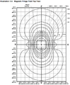 Gauss-lines for a generic install (top view).
 -
 Gauss-lines for a generic install (side view).
 -
 Gauss-lines for a generic install (front view).
 -
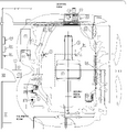 Sketch of gauss-lines for our particular installation.


When positioning equipment in the scan room, it's useful to be aware of the magnetic field lines. All equipment in the CNI scan room is MR-safe, but not all equipment functions properly in very high-field regions. The diagrams show the estimated field lines in the MR suite area.